-

-
400 South Salina St. Suite 201,
Syracuse, NY 13202

UNDERSTANDING FIBER OPTIC LOSS BUDGETS

With today’s IT hardware demanding faster and faster computing speeds, the miniscule fiber optic loss budgets for high-speed topologies, such as 400Gb Ethernet and 256Gb Fibre channel, are a real challenge for data center (DC) managers looking to implement and maintain a manageable cabling infrastructure. Even more challenging is building a structured cabling system that supports not only current speeds, but the increased data rates required from the Ethernet Alliance and Fibre Channel Industry Association.
With these considerations, is it possible to design a fiber optic structured cabling infrastructure to support a life cycle of 10 to 15 years without having to significantly reconfigure or redo the physical layer infrastructure? It is possible, but there are several factors to consider in order to ensure success.
The fiber optic link loss budget formula
The fiber optic link loss budget formula is the crux of success for optimal infrastructure support. The total loss budget is defined as the total acceptable amount of optical/signal power loss (expressed in decibels) that a fiber optic link can sustain and still operate error-free.
A ‘link’ is defined as the path of the cable between the transmitter and the receiver. Link loss budgets are measured based on the amount of attenuation, or signal reduction, related to the distance and number of connectors in the link. Prior to designing or installing a fiber optic link, the path and connections should be calculated for maximum or worst-case loss.
Acceptable fiber optic link loss budgets are defined by the various published speed standards from groups like the Institute of Electrical and Electronics Engineers (IEEE) and the Fibre Channel Industry Association (FCIA). These two standards address speeds from 1Gb to 400Gb for Ethernet and 4Gb to 128Gb Fibre Channel.

Factors for attenuation
While connecting points are the primary culprits for attenuation, there are other factors interacting with the link that contribute. A more comprehensive list of these includes:
- Absorption, scattering, or impurities in the glass
- The distance from end to end of the link
- The design of the fiber optic cables/cabling infrastructure/stressing the cable
- The number of connectors, splices, and coupler systems in a link
- Inferior product design
- Degradation in the transceivers/active components
- Aging passive components
- Exceeding bend radii
- End-face contamination
Understanding the standards
A decade ago, the published IEEE 802.3ba standard and its updated version, IEEE 802.3bm, introduced 100G Ethernet into the data center space. The next IEEE Ethernet standard, 802.3cd, addressed supporting speeds of 50/100/200Gb. Soon after arrived 802.3bs, which addressed speeds of 200Gb and 400Gb Ethernet. In 2018, Fibre Channel went from Generation 6 to Generation 7, with 64Gb speeds on duplex connections to 256Gb on parallel connections. The need to support higher speeds has already arrived.
Figure 1 shows the specified link loss budgets for Ethernet and Fibre Channel at various speeds.

The advantage of planning
Data center managers, when planning a new cabling system and considering these higher speeds, need to design and execute wisely. Serious cabling considerations for these new high-speed Ethernet and Fibre Channel topologies is a must.
How will the current or legacy DC look and perform? Will a portion of the existing cabling structure be reused, or will it be an all-new install? Will it be point-to-point cabling (aka home run connections) or a customized structured cabling system with port replication?
End-users and manufacturers relay again and again that cabling infrastructure is the culprit of a great deal of hardware outages. This is further verification that thoughtful planning and increased financial investment in cabling will result in a strong ROI.
Connector loss and supportable distances
Starting at 10Gb Ethernet and 8Gb for Fibre Channel, the loss budgets are already very small at 2.6 dB total link loss. 2.2 dB of that is associated with interconnect loss.
As we progress up into the 256 Gb Fibre Channel and 400 Gb Ethernet spectrum, those losses drop to 1.9 dB total link loss with the connector loss of 1.5 dB to 1.0 dB. These higher speeds leave very little margin for error in fiber optic infrastructure components, and insertion loss is a critical performance parameter in data center cabling measurements. Total connecter loss and the overall loss budget is taxing the data center to operate error-free and perform over supportable distances.
Supportable distances for these new high-speed requirements for Ethernet and Fibre Channel is shrinking to between 100 meters and 150 meters on multimode fiber. Most data center links won’t exceed this distance.
Attenuation of OM4, per the TIA-568 standard, at 850nm is 3.5 dB/KM. We can estimate 0.4dB as standard loss in our calculations per the distance spec of the link. This distance loss can be further tuned in extenuating circumstances if the link is shorter than the maximum standard, giving us more room within the link loss budget for speed.
Structured cabling and the TIA-942 standard
When designing a data center infrastructure, the build-out and port replication guidelines published in the TIA-942-B data center topology standard will create a structured cabling solution. This standard serves as a baseline for anyone who wishes to design and build a reliable and efficient data center.
Meeting this standard requires that the system have interconnects. These interconnects are critical to managing the high port density requirements of today’s data centers.
It’s prudent to eliminate any contributing factors that would introduce loss into a link that isn’t native to the installed fiber optic cabling plant or its connectors, splices, or any of the components. Even small loss points of 0.1 and 0.2dB add up very quickly.
Following the industry standards for interconnect loss (TIA-568), the LC connector has a standard of 0.5dB per mated pair, and the MPO has 0.75dB per mated pair. Considering a scenario featuring a basic link of two MPO-LC cassette modules between an MPO to MPO fiber optic trunk, the maximum dB loss will equate to -2.5db.
This is 1dB over the specification for interconnects in the link to support 100G. In this scenario, it’s easy to see how it doesn’t take many interconnects to significantly be at or above the 40Gb spectrum minimum loss requirements, without the hope of ever achieving 400Gb (see Figure 1).
How to future-proof your cabling
With these factors in mind, it’s only natural to ask how can we create a stable long-term infrastructure in such a fast-moving environment? Is it necessary to go back to (or stay with) a point-to-point cabling design and the headaches that come with a spaghetti mess, such as locating cable termination points, dealing with slack that can be caught and pulled, and the resulting errors that cause downtime and perhaps critical loss?
Not only is this option a management nightmare but, in most cases, it will add loss to the link with improperly deployed cabling. Worse, it will not be migratable for the future speeds or topologies, leaving future investments still pending.
So how do you future-proof your data center cabling infrastructure? It is recommended that prior to designing or installing a fiber optic system, a link loss budget analysis be conducted of the passive components making up the end-to-end fiber optic links in the system.
Be conservative when conducting this link loss budget analysis. The various link loss budget specs from Ethernet, Fibre Channel and InfiniBand are readily available and provide maximum loss figures (see Figure 1). It is best practice to design the link out to only 70% of the maximum loss budget stated. This conservative approach will help ensure the connected equipment will work over the installed fiber optic link.
Design challenges
The first challenge in creating the design of the link is the standard loss ratings assigned to the components needed. Research is a must. Standard ratings alone should not be the final guideline for product selection.
Standards organizations work to be universal and unbiased, thus allowing for choice of manufacturers for end-users. This results in a standard that offers a minimum recommended requirement for performance and a starting point reference. To ensure a design that leaves headroom in the link budget, products should be used that exceed these industry standards.
Higher-quality, low dB loss fiber interconnects, such as LC and MPO and their components, will come at a cost increase. The reason for this is because fiber optic termination is a labor intensive process, even for the most technologically advanced manufacturers.
Proper core termination requires a skilled and knowledgeable workforce. The process itself is very unforgiving of mistakes; a cable will go through multiple build steps and check points before being terminated with a connector. Yet even in the final test, if performance doesn’t meet expectations there is little that can be done. Most of this ‘defective’ subset will need to have the connector removed and the process started again.
Allowing for higher dB loss will mean less waste and lower costs. Higher expectations increase cost for better performing product.
Research will turn up companies that offer quality products with low dB loss and documentation to verify these performance results. For the most flexibility in design, locate products that offer 0.15-0.25dB for LC and 0.20-0.35 for MPO per mated pair. You will be able to deploy a manageable fiber infrastructure that will last the next 10 to 15 years and significantly exceed the industry standards.
Estimating link loss budgets
Estimating link loss budgets can be accomplished easily. First, find the allowed link loss budget per speed of transmit (see Figure 1). Use this to calculate the typical expected total link loss from the length of the fiber optic link, and then add up all of the interconnects. Keep in mind, splices will need to be calculated as well, but they are highly unusual in a data center.
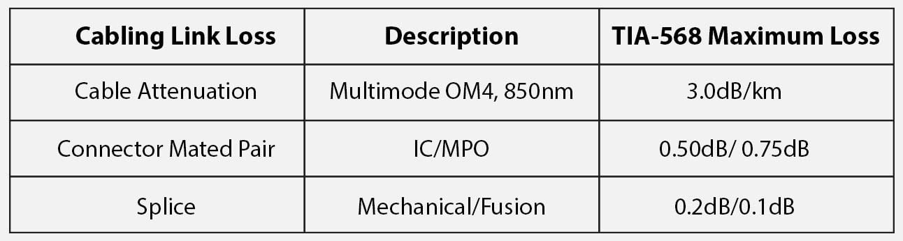
Figure 2
This calculation will give a close estimate to what the link loss budget could be. However, when implementing this link at the speed required in a real-world scenario, there are other considerations relating to loss that can improve actual performance:
- Quality components manufactured for performance and reliability
- Best practices installation of the infrastructure design maintaining proper bend radii and efficient cable routing
- Inspection of the fiber end faces and cleaning as necessary prior to installation
- Plan an acceptable dB buffer into the calculation
- Transceiver effectiveness
Note that loss budget allowances for network/SAN/InfiniBand equipment may depend on the difference between the sensitivity of the receiver and output of the transceiver into the fiber.
Degradation of the sources or transceiver over time is a factor that many forget or aren’t aware of. Again, make sure there is ample head room in the link loss budget and design to a maximum of 70% of the standard link budget.
The quality of fiber optic connectors and splice terminations in the infrastructure may also degrade over time. Some field-installable connectors and mechanical splices wear, and the index matching gel degrades, which can contribute to higher losses.
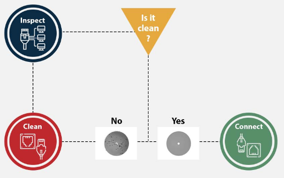
Connectors can get dirty or contaminated, even if best practices are followed. With the fiber diameter of less than a human hair, contamination is not easily avoided. Consider data centers in very low humidity locations where static charges on connector ferrules attract particles and dirt, even after cleaning. Figure 3 shows best practices for fiber optic end face cleaning.
Figure 3
Consideration of all the factors involved in contributing to loss, or the elimination of loss, will ultimately allow you to build a fiber optic structured cabling system according to the TIA-942 standards and be comfortably under the 400G loss budget requirement. See Figure 4 below for example.
Figure 4
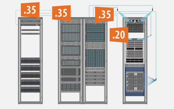
This example features seven interconnects with only 1.25dB of loss.