

As is often the case with layer one connectivity, the cabling for inter-chassis links (ICLs) can be an afterthought. Before we...
As is often the case with layer one connectivity, the cabling for inter-chassis links (ICLs) can be an afterthought. Before we get to the cabling, let’s look at what ICL ports are and why they are used.
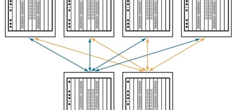
In short, ICL ports allow you to connect two chassis together to ensure redundancy. For those reading who are a little more savvy and experienced in the data center, you may remember the old Daisy Chain topology, which allowed you to connect multiple devices in the same link. Think of ICLs and Daisy Chain as cousins. See Diagram A below for an example.
Diagram A
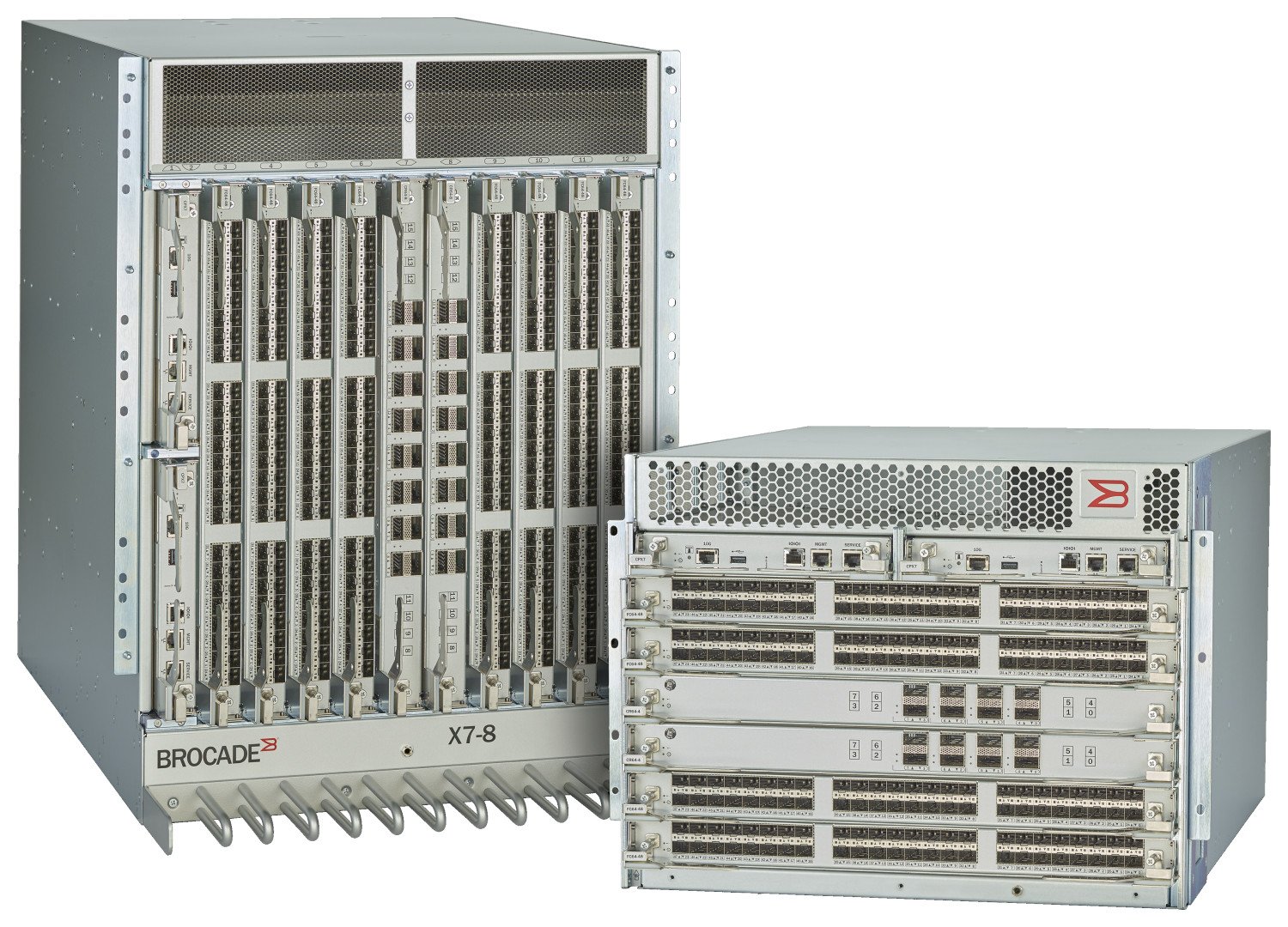
ICL ports can be found on the chassis’ core routing blades. Looking at Broadcom’s recently launched Gen7 portfolio, the X7-8s accommodate 16 ICL ports per blade (32 total) while the X7-4s accommodate eight ICL ports per blade (16 total).
Organizations must adapt to continuous data growth with storage environments that can easily scale to meet their business needs. Broadcom chassis connectivity utilizes dedicated ICLs to connect up to 12 directors, simplifying fabrics that increase consolidation while reducing complexity and costs.
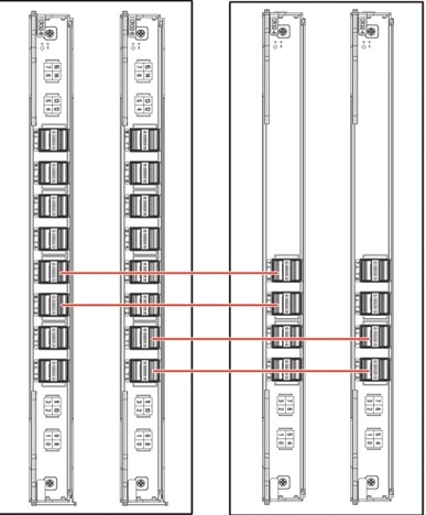
Because the ICL connections reside on the core routing blades, instead of consuming ports on the port blades, up to 33 percent more device ports are available for server and storage connectivity. This maximizes overall port density within the smallest amount of rack space while freeing up front-facing device ports for server and storage connectivity. See Diagram B below for an example.
Diagram B
The Fun Part
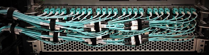
Now let’s get to the fun part: cabling!
The X7 supports cable distances up to 10 km at 32Gb/s using the LWL optic in a Gen 7 blade. These ICL kits can provide connectivity for Gen 7 to Gen 7, Gen 7 to Gen 6, or Gen 7 to Gen 5.
For most applications in the data center, you will be using Short-Wave ICLs. Either Gen 7 to Gen 7 at a 4x64Gb/s, or Gen 7 to Gen 6 at 4x32Gb/s, or Gen 7 to Gen 5 at 4x16Gb/s, all supporting distances up to 100 meters.
In all of these aforementioned scenarios, the ICL QSFPs require an OM4 12-fiber MTP (MPO) Female/Female assembly limited to 100M. MTP is the US Conec brand of the industry-standard MPO connector (think of Kleenex being a brand of tissues).
For longer-distanced situations, the Long-Wave ICLs would be used. Differentiating from the Short-Wave ICLs, beginning with Broadcom’s Gen 5 portfolio (8510-4 and 8510-8s), these require an LC connector and would use a single-mode LC/LC fiber jumper for ICLs.
To simplify connectivity and make it easier to manage, CABLExpress recommends utilizing structured cabling and patch panels when implementing. This is especially true in scenarios where the chassis switches might be in separate rows or locations in the data center. Using the LW ICLs, your switches could be on different floors or PODs in the data center.
Running long cables directly connecting ICL optics in these situations limits your flexibility when performing any moves, adds, or changes.
Let’s walk through two scenarios to optimize your ICL environment.
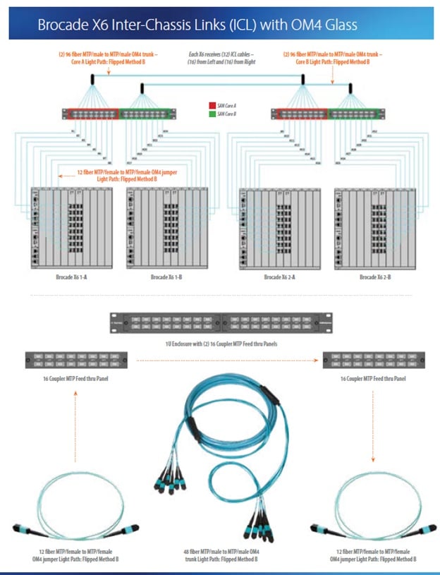
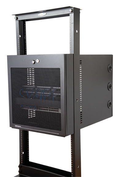
Scenario 1: X6/X7 - X6/X7 with SW QSFP ICL Optics
In the design depicted in the image to the right, the following CABLExpress solutions are utilized:
- CABLExpress 96-Fiber MTP Male/MTP Male OM4 Trunks
- H-Series 1U Enclosures
- 16-MTP Adapter Panels
- CABLExpress 12-Fiber MTP Female/MTP Female OM4 Trunks
To segment the connectivity, we recommend running the 96-fiber trunks as your “highway,” so you can run short MTP/MTP Jumpers into the ICL optics.
For example, instead of running a 50M ICL assembly directly connecting each active port, you can run the 96-fiber trunks to “set it and forget it.”
This allows you to do your growth with the short jumpers making it easier when later adding more ICL ports. You will minimize installation time in the future and eliminate risk variables.
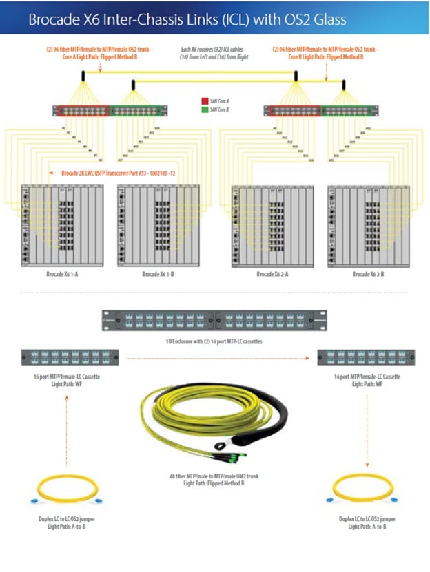
Scenario 2: X6/X7 - X6/X7 with LW QSFP ICL Optics
Similar to scenario 1 above, scenario 2 will utilize structured cabling and patch panels:
- CABLExpress 96-Fiber MTP Female/MTP Female OS2 SM Trunks
- H-Series 1U Enclosures
- 16-port MTP/LC Cassette Modules
- CABLExpress Duplex LC/LC SM Fiber Jumper
Again, we recommend setting up a “highway” in this scenario using 96-fiber MTP/MTP Trunks. But since the SM LW ICL Optics use an LC interface, we suggest using MTP/LC cassette modules.
This will allow you to add LC/LC jumpers as you add more ICL ports. As mentioned previously, environments using the SM LW ICL optics often have their SAN Directors further apart because of the exponential distance limitation.
Never downplay the importance of cabling
Budgets, resources, timing, and many other factors are involved when planning and prioritizing data center projects. In the early days, it wasn’t necessary to spend much time planning your cabling infrastructure.
Back then, options were limited, copper cabling was difficult to break, and costs were minimal. These days, data speed and access requirements have increased costs of implementation, materials and design requirements, as well as soft costs that come into play with MACs, troubleshooting errors, and installation issues.
When cabling is planned and installed according to best practices, variables for issues and hurdles will be minimized in these high-profile projects.
Recent Posts
Ensuring Uncompromised Security
The Problem:Data...
In a significant leap forward for data center...
Effective cable management is not just about...
Popular Posts

Why does the gauge matter in my network’s racks?...
When you are building a network that requires...
In the cable world, the term structured cabling...